In dynamic system real time simulation, the simulation time is synchronous or proportional to the real time, so that to simulate man operating or to observe the actual response of the system.
Sample: PID controller real time simulation
As steps of last chapter, add two component from interactive package to the project.
Interactive -> ToggleSwitch
ToggleSwitch is used to switch different output to downstream network by hand.
9 setting values maximum can be inputed to this component. If two values in turn are the same, then the values from the second value will be ignored.
In this sample, the setting values is as follows:
| X1 | 50 |
| X2 | 40 |
| X3 | 30 |
| X4 | 20 |
| X5 | 10 |
| X6 | 0 |
| X7 | -10 |
| X8 | -10 |
| X9 | 0 |
| INV | 3 |
INV=3 ,means the initial setting number is, namely X3.
It's output S2 is connected to the input ST of Step_0, so the input value of Step_0 will be taken by ToggleSwitch->S2.
Interactive -> FloatChart
FloatChart is used to output real time parameter changing curve.
4 plot parameters maximum can be inputed in this component. One parameter used in this sample.
Connect output S2 of SCurve_0 input Y1 of this component, other inputs are as follows:
| X | 0 |
| Y2 | 0 |
| Y3 | 0 |
| Y4 | 0 |
| YMIN | 0 |
| YMAX | 0 |
| XLEN | 5 |
| TR | 0.02 |
| SHOW | 1 |
X=0 means the X axis is represent time.
YMIN and YMAX is the range of Y axis, if YMIN=YMAX, the range is adjusted automatically.
XLEN is display length of X axis, which is "s" second.
TR is refresh time interval of the curve chart.
SHOW=1 means the plot window is visible, SHOW=0 means hide.
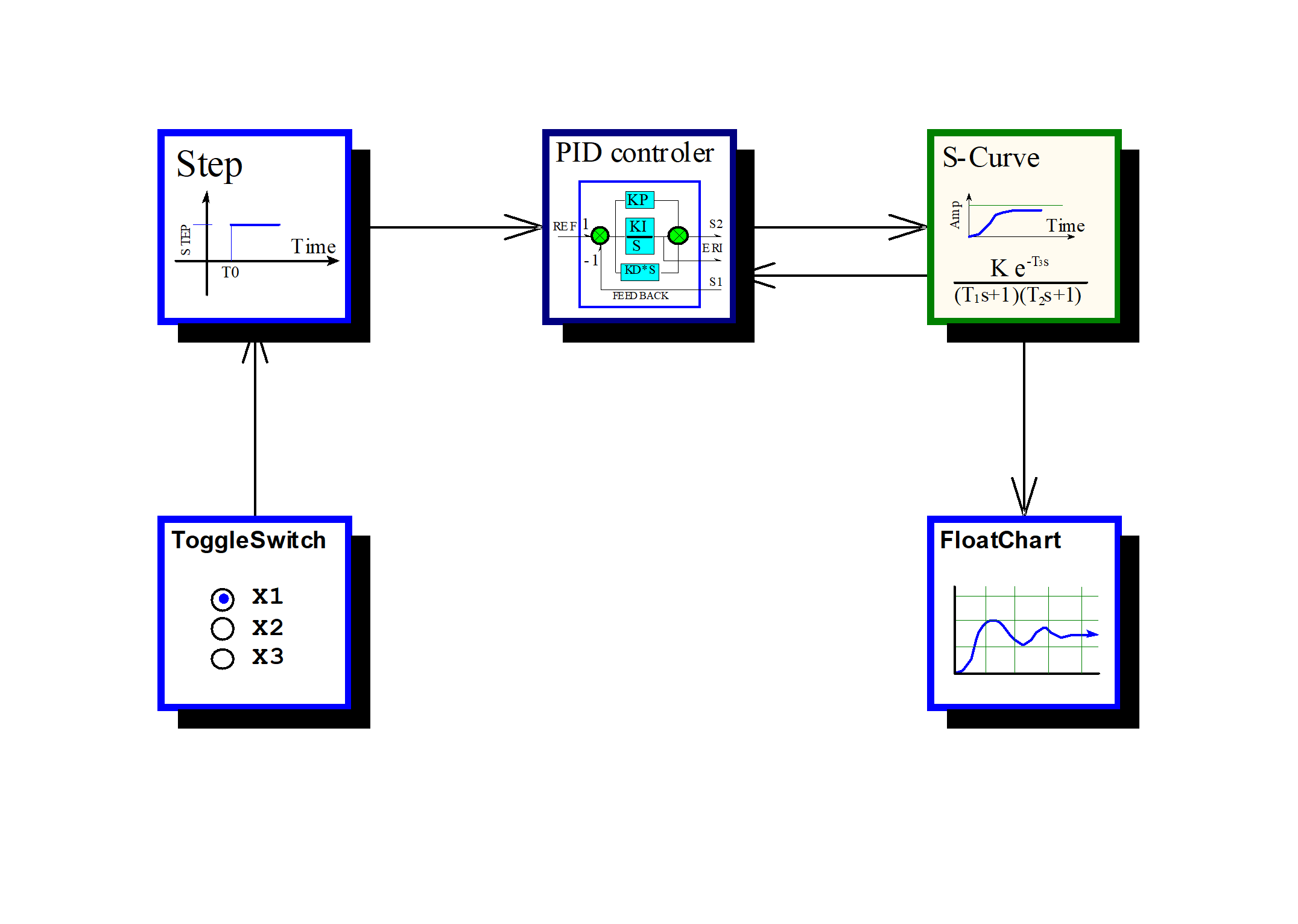
Project system network is as follow:
Click "Real time simulation" speed button toolbar or from menu, the following dialog pops up:
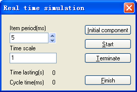
Set real time simulation time interval to 5ms(This value will be changed if computer performance is insufficient), set time scale to 1(Same to real time).
Click "Initial" button, the interactice component windows will be initialized, and displayed by requiring. Drag the window to proper place in screen.
Click "Start" button, the real time simulation begins to run. Operating to interactive component window will influence system response, this can be seen on real time output plot curve.
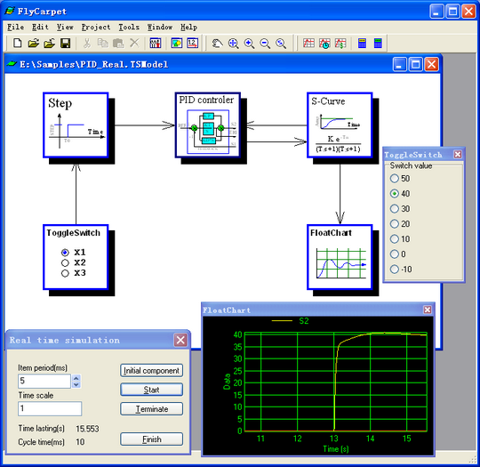
Click "Terminate" button to stop the process, of click "Finish" button to exit it.
A FlyCarpet package is a collection of components. A FlyCarpet project can include multiple same state components.
-
Math
General state, mathematical and logical functions.
-
General
Dynamic state, general components for dynamic simulation.
-
Interactive
Dynamic state, interactive components for dynamic simulation.
-
DuctNet
Static state, duct network calculation.
-
Refrigeration
Static state, refrigeration system design and optimization.
-
ECSOptim
Static state, airplane Environmental Control System(ECS, or A/C system) design and optimization.
-
HXFinPlate
Static state, Fin-Plate style heat exchangers design and simulation.
-
VacuumDesign
Static state, steam eject steel furnace vacuum pump design and optimization.
These tools are used to reduce developing time for package and its components so that developers can focus on the core component logic design.
-
FCPBuilder
A fast package and components c++ code generating tool based on inputs, outputs settings and logic processing code.
-
MetaBuilder
A specific metafile builder for FlyCarpet component.